| 规格 |
|
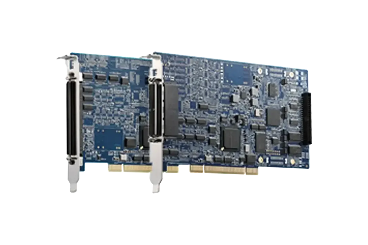
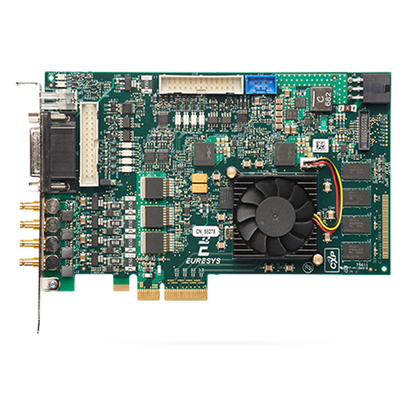
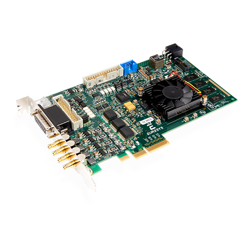
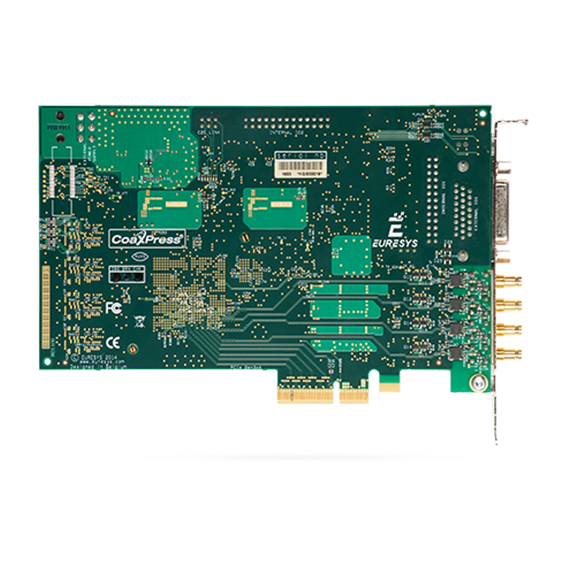
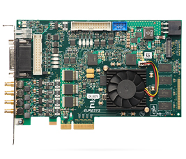
| Form Factor | PCI Express card |
Format | Standard profile, half length, 4-lane PCI Express card |
| Cooling method | Air cooling, fan-cooled heatsink |
| Mounting | For insertion in a standard height, 4-lane or higher, PCI Express card slot |
Connectors | 'A', 'B', 'C', 'D' on bracket: EXTERNAL I/O' on bracket: INTERNAL I/O 1' and 'INTERNAL I/O 2' on PCB: 'AUXILIARY POWER INPUT' on module: 'C2C-LINK' on module:
|
Lamp indicators | 'A', 'B', 'C', 'D' on bracket: 'FPGA STATUS LAMP' on PCB: Bi-color red/green LED FPGA status lamp
'BOARD STATUS LAMP' on PCB:
|
Switches | 'RECOVERY' on card PCB: |
| Dimensions | L 167.65 mm x H 111.15 mm
L 6.6 in x H 4.38 in |
| Weight | 180 g, 6.35 oz |
| Host bus |
|
| Standard | PCI Express 3.0 |
| Link width | |
| Link speed | |
| Maximum payload size | 512 bytes |
| DMA | 32- and 64-bit |
| Peak delivery bandwidth | 3,900 MB/s |
| Effective (sustained) delivery bandwidth | 3,350 MB/s (Host PC motherboard dependent) |
| Power consumption | Typ. 16.8 W (3.8 W @ +3.3V, 13 W @ +12V), excluding camera and I/O power output |
| Camera / video inputs |
|
| Interface standard(s) | CoaXPress 1.0 and 1.1 |
| Connectors | 4x DIN1.0/2.3 CXP-6 |
| Status LEDs | 1 CoaXPress Host connection status per connector |
Number of cameras | One 1- or 2- or 4-connection area-scan camera Two 1- or 2-connection area-scan cameras Four 1-connection area-scan cameras One 1- or 2- or 4-connection line-scan camera Two 1- or 2-connection line-scan cameras Four 1-connection line-scan cameras
|
| Line-scan cameras supported | Yes |
| Maximum aggregated camera data transfer rate | 25 Gbit/s (2,500 MB/s) |
| Supported CXP down-connection speeds | 1.25 GT/s (CXP-1), 2.5 GT/s (CXP-2), 3.125 GT/s (CXP-3), 5 GT/s (CXP-5), and 6.25 GT/s (CXP-6) |
| Number of CXP data streams (per camera) | 1 data stream per camera |
| Maximum CXP stream packet size | 16,384 bytes |
PoCXP (Power over CoaXPress) | |
Camera types | Area-scan cameras: Line-scan cameras:
|
Camera pixel formats supported | Raw, Monochrome, Bayer, RGB, and RGBA (PFNC names):Raw Mono8, Mono10, Mono12, Mono14, Mono16 BayerXX8, BayerXX10, BayerXX12, BayerXX14, BayerXX16 where XX = GR, RG, GB, or BG RGB8, RGB10, RGB12, RGB14, RGB16 RGBA8, RGBA10, RGBA12, RGBA14, RGBA16
|
| Area-scan camera control |
|
Trigger | Precise control of asynchronous reset cameras, with exposure control. Support of camera exposure/readout overlap. Support of external hardware trigger, with optional delay and trigger decimation.
|
| Strobe | |
| Line-scan camera control |
|
Scan/page trigger | Precise control of start-of-scan and end-of-scan triggers. Support of external hardware trigger, with optional delay. Support of infinite acquisition, without missing line, for web inspection applications.
|
Line trigger | Support for quadrature motion encoders, with programmable noise
filters, selection of acquisition direction and backward motion
compensation. Rate Converter tool for fine control of the pixel aspect ratio:
Rate Conversion Ratio in the range 0.001 to 1000 with an accuracy
better than 0.1%. Rate Divider tool
|
| Line strobe | Accurate control of the strobe position for strobed light sources. |
| On-board processing |
|
| On-board memory | 1 GB |
Image data stream processing | |
Data stream statistics | |
Event signaling and counting | The application software can be notified of the occurrence of various events: Custom events sources: I/O Toolbox events Camera and Illumination control events CoaXPress data stream events CoaXPress host interface events
Each custom event is associated with a 32-bit counter that counts the number of occurrences The last three 32-bit context data words of the event context data can be configured with event-specific context data:
|
Input LUT (Lookup Table) | Available for monochrome cameras8 to 8 bits 10 to 8, 10 or 16 bits 12 to 8, 12 or 16 bits
|
| General Purpose Inputs and Outputs |
|
Number of lines | 20 I/O lines:4 differential inputs (DIN) 4 singled-ended TTL inputs/outputs (TTLIO) 8 isolated inputs (IIN) 4 isolated outputs (IOUT)
|
Usage | Any I/O input lines can be used by any LIN tool of the I/O Toolbox Selected pairs of I/O input lines can be used by any QDC tool of the I/O toolbox to decode A/B signals of a motion encoder The LIN and QDC tools outputs can be further processed by the
other tools (DIV, MDV, DEL) of the I/O toolbox to generate any of the
following "trigger" events: The "cycle trigger" of the Camera and Illumination controller The "cycle sequence trigger" of the Camera and Illumination controller The "start-of-scan trigger" of the Acquisition Controller (line-scan only) The "end-of-scan trigger" of the Acquisition Controller (line-scan only)
|
Electrical specifications | DIN: High-speed differential inputs compatible with
ANSI/EIA/TIA-422/485 differential line drivers and complementary TTL
drivers TTLIO: High-speed 5V-compliant TTL inputs or LVTTL outputs,
compatible with totem-pole LVTTL, TTL, 5V CMOS drivers or LVTTL, TTL, 3V
CMOS receivers IIN: Isolated current-sense inputs with wide voltage input
range up to 30V, compatible with totem-pole LVTTL, TTL, 5V CMOS drivers,
RS-422 differential line drivers, potential free contacts, solid-state
relays and opto-couplers
|
| Polarity control | Yes |
Filter control | |
| Power output | Non-isolated, +12V, 1A, with electronic fuse protection |
I/O Toolbox tools | The I/O Toolbox is a configurable interconnection of tools that
generates events (usually triggers) from input lines. The composition of
the toolset is product- and firmware-dependent.Line Input tool (LIN): Edge detector delivering events on rising or falling edges of any selected input line. Quadrature Decoder tool (QDC): A composite tool including: A quadrature edge detector delivering events on selected transitions of selected pairs of input lines. An optional backward motion compensator for clean line-scan image acquisition when the motion is unstable. A 32-bit up/down counter for delivering a position value.
Divider tool (DIV): to generate an event every nth input events from any I/O toolbox event source. Multiplier/divider tool (MDV): to generate m events every d input events from any I/O toolbox event source. Delay tool (DEL): to delay up to 16 events from one or two I/O
toolbox event sources, by a programmable time or number of motion
encoder ticks (any QDC events). User Actions Scheduler tool (UAS): to delegate the execution of
User Actions at a scheduled time or encoder position. Possible user
actions include setting low/high/toggle any bit of the User Output
Register or generation of any User Events.
|
I/O Toolbox composition | Firmware-dependent I/O toolbox composition:1-camera: 8 LIN, 1 QDC, 1 DIV, 1 MDV, 2 DEL, 1 UAS 2-camera: 8 LIN, 2 QDC, 2 DIV, 2 MDV, 2 DEL, 1 UAS 4-camera: 8 LIN, 1 UAS 1-line-scan: 8 LIN, 1 QDC, 1 DIV, 1 MDV, 2 DEL, 1 UAS 2-line-scan: 8 LIN, 2 QDC, 2 DIV, 2 MDV, 2 DEL, 1 UAS 1-slm-camera: 8 LIN, 1 QDC, 1 DIV, 1 MDV, 2 DEL, 1 UAS 1-sls-camera: 8 LIN, 1 QDC, 1 DIV, 1 MDV, 2 DEL, 1 UAS
|
| C2C-Link |
|
Description | |
Specification | |
| Software |
|
Host PC Operating System | Microsoft Windows 10, 8.1, 8, 7 for x86 (32-bit) and x86-64 (64-bit) processor architectures Linux kernel versions 3.10 to 4.13, compatible with a wide
range of distributions, tested with CentOS 7, Ubuntu 14.04 and Ubunto
17.04, for x86 (32-bit) and x86-64 (64-bit) processor architectures Linux kernel version 3.10.96-tegra, tested with Ubuntu 16.04 LTS, for aarch64 (64-bit) processor architecture
|
APIs | EGrabber class, with C++ and .NET APIs:GenICam GenTL producer libraries compatible with C/C++ compilers:x86 dynamic library designed to be used with ISO-compliant C/C++ compilers for the development of x86 applications x86_64 dynamic library designed to be used with ISO-compliant C/C++ compilers for the development of x86_64 applications aarch64 dynamic library designed to be used with ISO-compliant C/C++ compilers for the development of aarch64 applications
|
| Memento | Compatible with Memento Event Logging tool |
| Environmental conditions |
|
| Operating ambient air temperature | 0 to +55 °C / +32 to +131 °F |
| Operating ambient air humidity | 10 to 90% RH non-condensing |
| Storage ambient air temperature | -20 to +70 °C / -4 to +158 °F |
| Storage ambient air humidity | 10 to 90% RH non-condensing |
| Certifications |
|
| Electromagnetic - EMC standards | |
| EMC - Emission | EN 55022:2010 Class B FCC 47 Part 15 Class B
|
EMC - Immunity | EN 55024:2010 Class B EN 61000-4-3 EN 61000-4-4 EN 61000-4-6
|
| Flammability | PCB compliant with UL 94 V-0 |
| RoHS | European Union Directive 2011/65/EU (ROHS2) |
| REACH | European Union Regulation 1907/2006 |
| WEEE | Must be disposed of separately from normal household waste and must be recycled according to local regulations |
|
|